DELTA Solution Series - Part 2: Temperature Measurement is Challenging
In DELTA Solution Series Part 1, we talked about all the things that can make an object appear hotter or colder than it really is when compared to its surroundings. Emissivity, the efficiency with which something gives off its thermal energy, and reflectivity, the degree to which an object reflects the thermal energy around it, are the primary variables we must consider. These are primarily determined by what a material is made of and its surface condition.
Emissivity and reflectivity, however, don’t just impact how relatively hot or cold things look, they also determine whether temperature measurements are truly accurate. Let’s look at what we must adjust in the camera’s settings in order to get accurate temperature measurements.
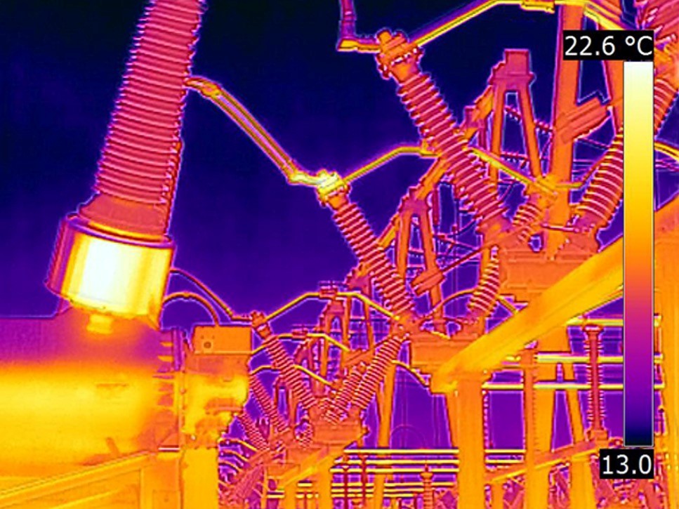
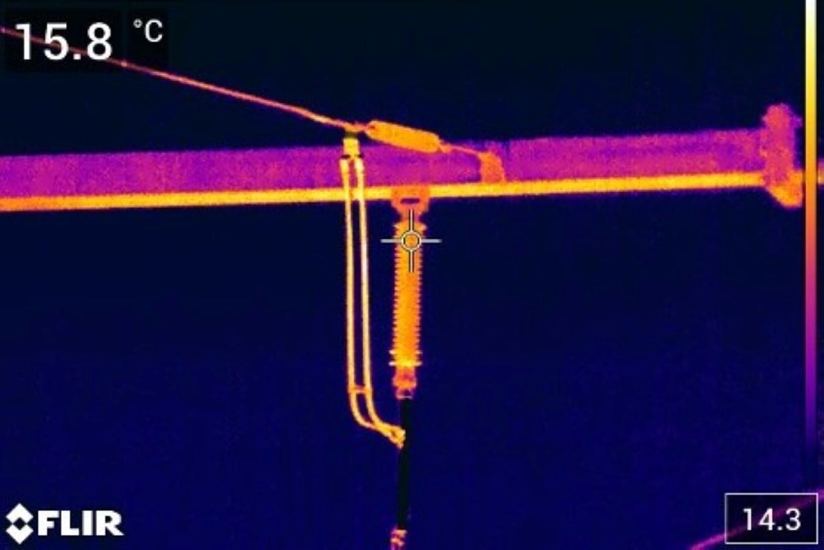
Figure 1. Radiometric thermal cameras provide the temperature of every pixel in the scene
Radiometric Thermal Cameras: Apparent versus True Temperature
First, let’s say something about what makes a camera radiometric, or the ability to measure temperatures. All thermal cameras are technically radiometers – they are sensitive to varying intensities of radiation; but, radiometric cameras take that a step further thanks to the factory calibration process they experience. During the build process, radiometric cameras are pointed at a series of radiation sources. Each of these sources, called blackbodies, are set to produce an amount of energy that corresponds to a specific temperature. Each of these sources are programmed into the camera to create what is called a calibration curve. This is the internal reference the camera uses as the basis for its temperature calculations.
Now that we’re working with a calibrated, radiometric camera, let’s talk about the two different types of temperature measurements we can get – apparent temperature and true temperature. An apparent temperature is an uncompensated temperature reading, meaning that correct values for emissivity and reflected apparent temperature are left at default values. Typically the emissivity is set at 1.0 or .95 and the reflected apparent temperature is left at 20 °C or 68 °F. These apparent temperature values have little to no relationship to the object’s actual temperature. They might be close, but they could just as easily be off by hundreds of degrees.
A true temperature, on the other hand, is one where the operator has compensated for emissivity, reflected apparent temperature, and – if possible – atmospheric impacts. If these factors are changed in the camera’s menu, the temperature readings on the screen should be within the camera’s accuracy specification.
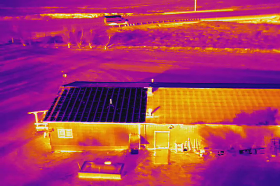
Figure 2. Different roof materials with different emissivity significantly impact thermal camera reading
How do we know the emissivity of a material? The best way, though the most complicated method, is to measure an object’s emissivity by comparing that object to another that has a known emissivity and is at the same temperature. Knowing how to do this is one of the main reasons people take thermography certification courses at the Infrared Training Center (ITC). The other way is to look up materials on an emissivity table. These are widely published online, though keep in mind that they may or may not be accurate for the thing operators may measure out in the real world, so be sure to cite the source of the emissivity value when reporting results.
Table 1. Example of online emissivity tables that provide estimated emissivity for a wide variety of items
| Material | Emissivity |
| Burnt Toast | 1.0 |
| Asphalt | 0.95 |
| Iron (oxidized) | 0.7 |
| Water | 0.93 |
| Beef Fat | 0.78 |
Reflected apparent temperature (often abbreviated as Trefl) is also a measured value that is then entered in a camera’s menu. As the name implies, it is an apparent temperature, so measure it with the emissivity value set to 1.0. Next lay a reflective material next to the object in question and take an average temperature of the reflective material. Enter this value in the reflected temperature area of the camera menu and proceed to measure the object of interest.
As drone operators, the most commonly reflected thing in the images is the sky. Furthermore, the coldest thing in view is often the clear sky or a reflection of it. Incorrect compensation for Trefl can lead to massive errors in temperature measurements of reflective materials. A common mistake is confusing reflected apparent temperature for ambient temperature – they are not the same thing at all. For instance, when looking at solar panels, the Trefl could be as low as -40 °F on a clear day, but the ambient temperature could be above 90 °F. This very common error makes any temperature measurements – and the conclusions drawn from them – practically useless, and potentially catastrophic.
Determining the Right Spot Size
Another consideration is what’s called the camera’s spot size. A thermal camera cannot accurately measure the temperature of a single pixel for a variety of reasons. In general, thermographers need a minimum of a four-by-four-pixel square, but sometimes as many as 10-by-10 pixels. To get an accurate temperature measurement, make sure the drone is close enough to the target to place the camera’s measurement spot (that four-by-four-pixel square) completely inside the heat signature of the spot requiring measurement.
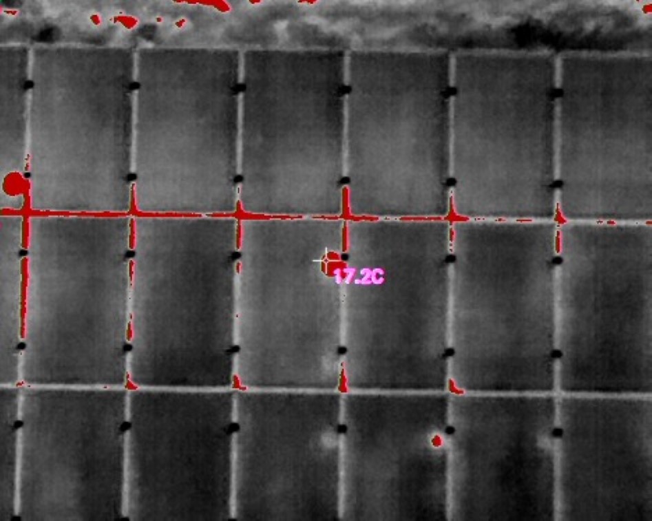
Figure 3. The measurement spot size must fit within the heat signature
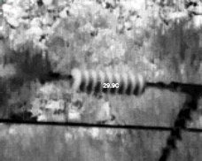
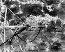
Figure 4. Adjust drone position to match measurement spot size to the fit within the heat signature
Unfortunately, the most common drone thermal cameras in use don’t provide an adequate visual reference to do this. The spot measurement tool is just a graphic highlighting a single pixel, which – as previously mentioned – will not give an accurate temperature measurement. What’s more, most thermal cameras only provide electronic zoom, which just makes the individual pixels larger and doesn’t provide added resolution.
Common Pitfalls for Drone Thermographers
All these items are often overlooked by drone thermographers. The most basic being that they assume the temperature readings they are seeing on the drone’s display are accurate. Ninety-nine percent of the time, they’re not even close. This is usually because of the combination of the emissivity and reflected apparent temperature being left at their default values, when those values bear no resemblance to the properties being encountered in the field. The other could be that they’re simply too far away from their object of interest to measure it accurately – remember, a single pixel cannot be measured accurately.
But something just as common is trying to provide quantitative data, with actual temperature values that claim to be accurate, when a qualitative analysis is all that’s required. A perfect example of this is a roof inspection. The goal of a thermal roof inspection is to find thermal anomalies that may indicate the presence of moisture trapped beneath the roof membrane. It is an inherently qualitative inspection in most cases.
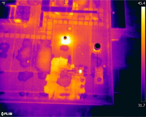
Figure 5. Roof inspections are a good example of qualitative analysis
To help ensure a successful thermal inspection, one of the first things to ask is, “What is the goal of the inspection?” If the mission calls for qualitative data, ignore the temperature values shown on the screen. However, if the mission requires quantitative data, the pilot should be trained and certified to collect emissivity and Trefl values accurately.
To learn more, please see www.flir.com/delta.
Related Articles
-
 Press Release
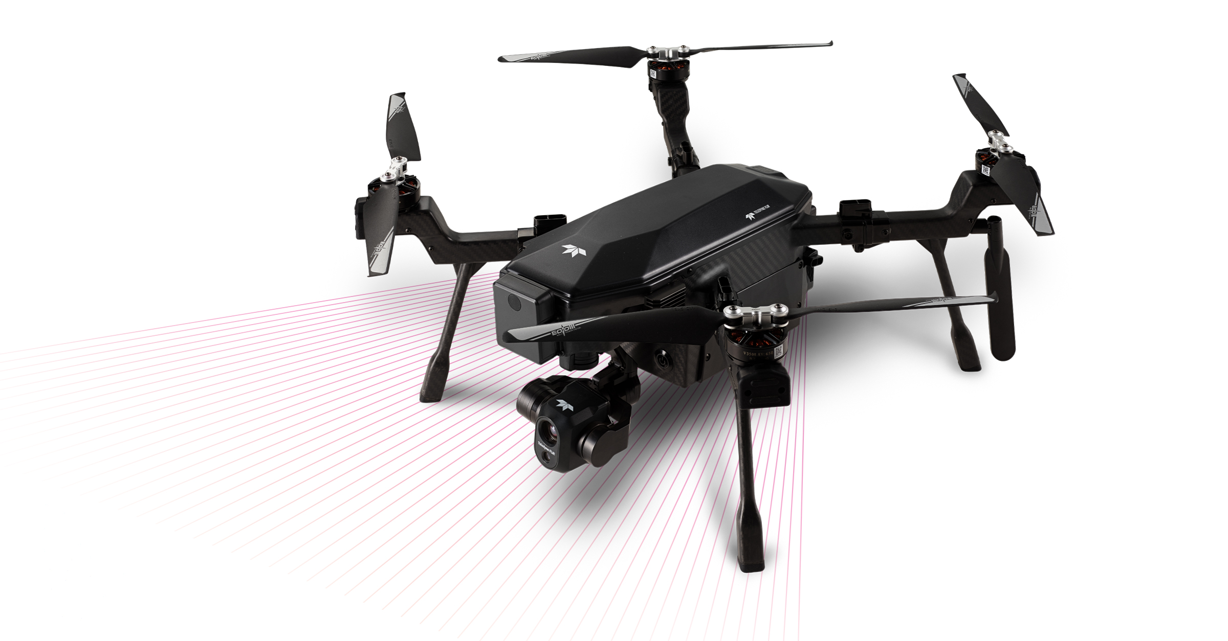
Teledyne FLIR debuts SIRAS Drone for Public Safety and Industrial Inspection
Read the story -
 Whitepaper
DELTA Solution Series - Part 3: Overhead Electrical Drone Inspections
Learn more -
 Whitepaper
DELTA Solutions Series - Part 4: Thermal Inspection of Solar Panels
Learn more