FLIR UAS IR Camera FAQ
Q: What is the difference between 30 Hz and 9 Hz?
A: Video cameras output a series of “still” images at a regular rate, a rate given in Hertz (Hz) or in frames per second (fps). FLIR UAS cameras with 25 to 60 fps video put out that number of unique frames each second. In order to make transportation of cameras across borders easier, a class of “<9 Hz” cameras is available. These cameras send out video frames at a normal rate, but these frames are duplicated for short intervals. This results in an effective frame rate of fewer than 9 fps. Please contact an export specialist before transporting any thermal camera from one country to another.
Q: Can I export or travel internationally with my thermal camera?
A: There are international regulations regarding the transportation and transfer of all thermal cameras. Export laws allow thermal cameras with frame rates less than 9 frames per second (fps) to be moved more freely across borders than 60 or 30 fps cameras. Contact an export specialist for details.
Q: What is the difference between 160 × 120, 336 × 256, and 640 × 512 resolution cameras?
A: Each FLIR UAS thermal camera has an imaging device known as a focal plane which converts the target image to pixels. The sizes 160 × 120, 336 × 256, and 640 × 512 are examples of the resolution options available for these cameras. The first value represents the horizontal pixel count and the second number represents the vertical pixel count. At a quick glance, many people assume the 640 is twice the resolution at a 336 but in fact, the total pixel count is 3.8x more. 336 × 256 delivers 86,016 total pixels and 640 × 512 delivers 327,680 pixels.
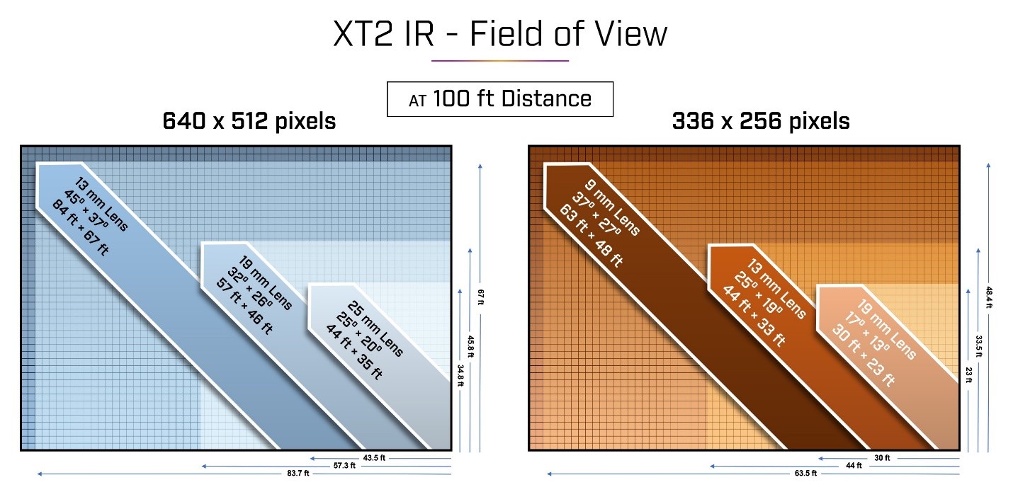
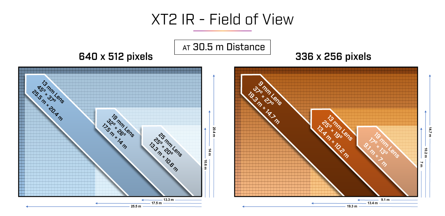
Q: What is the field of view?
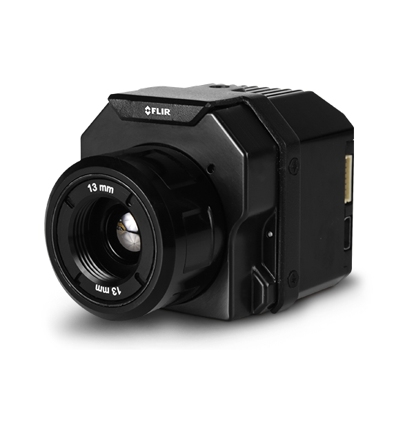
A: Field of view, also referred to as FOV, is the degree of visibility the camera lens delivers to the sensor. For example, each pixel in the 640 × 512, 13 mm configuration (45 × 37-degree FOV) will represent an angle of 0.07 degrees per pixel, meaning that at 100ft, each pixel is imaging 1.57 inches. From a less technical perspective, FOV equates to the observable area that can be imaged with the lens. The graphics below show how various FOVs in 640 and 256 cameras correspond to the observable area when looking straight down. The calculation is linear, so an elevation of 200 ft would double the value., while an elevation of 50 ft would be half of the value.
Q: What is the best lens for my operation?
A: There are two major considerations in determining the best lens and resolution for a given application. First, the field of view (FOV) is the approximate angle of the observable image. Figure 2 shows the observable area by lens model at 100 ft AGL assuming you are looking straight down.
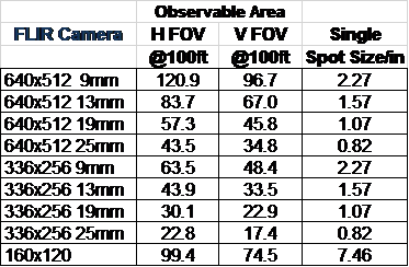
The second factor is the angle that each pixel represents, known as the iFOV. Knowing the angle of each pixel helps you calculate the number of pixels that would appear for various targets at various distances. For temperature measurement, an object should appear as at least a 5 × 5 pixel grid but 10 × 10 or more will yield even better results. A lens should be chosen so that the FOV is wide enough to find what you are looking for, and that the iFOV will allow enough “pixels on target” at the desired flight altitude. Figure 2 demonstrates spot size at 100 ft AGL when looking straight down. Globally, the 640 × 512, 13 mm option is the #1 selling model and performs most tasks very well.
Q: What should I buy?
A: Camera systems are often available as a package with a compatible drone. This is the easiest way to ensure compatibility. There are gimbal packages available that target specific cameras on specific drones or drone families. These may be available from the vehicle manufacturer or third parties, such as Gremsy. Documentation for each gimbal will identify which cameras and vehicles they support.
To integrate a general-purpose sUAS camera to your existing drone, a number of factors need to be considered.
Weight and center of gravity (CG): The drone must be able to lift the camera and still maintain a useful flight time. Some provisions need to be made in order to support the camera on the vehicle and maintain balance. FLIR UAS cameras usually have a ¼-20 threaded hole on either the top, bottom, or both sides of the camera. These holes are the same size and thread pattern found on consumer cameras so they can be used on tripods.
Electrical supply: Most FLIR cameras are designed to draw power directly from the vehicle battery, while others draw regulated 5 volts from a battery elimination circuit (BEC). The voltage and current requirements of each camera can be found in the datasheet or user guide for the camera.
Video: HDMI or composite video outputs may be available from the camera. If real-time video is needed for your mission, a compatible video downlink system must be provided.
Camera and gimbal control: Various features of the camera and any associated gimbal will need to be controlled. Often, this is done using servo PWM signals. These are three-pin outputs from flight controller or remote-control receiver that are used to control motor controllers, servo actuators, and other vehicle components.
GPS: Some cameras have built-in GPS receivers for geotagging image files. These receivers may need to be connected to external antennas, which are most often placed on top of the vehicle for the best possible satellite reception. Some cameras do not have internal GPS receivers, and if image files are to be geotagged, information from the GPS on the vehicle will need to be sent to the camera. Typically, this will be done using MAVLink. The engineering datasheet or user guide will list the available interfaces and their capabilities.
Q: Can I detect methane gas leaks with my thermal camera?
A: Gas-finding IR cameras work by detecting the absorption of light or heat energy by gasses. This absorption is typically weak and in a narrow spectrum, requiring specialized optical filters and high-quality sensors. General-purpose thermal will not reliably detect these gasses. Gas-finding cameras are specially designed with narrow optical filters and typically contain a cryogenic cooler, which draws additional power, and adds weight.
Q: How high can I fly with my thermal camera?
A: The maximum allowable altitude can be found under the environmental specifications on the product datasheet. While this is typically 38,000 feet MSL for most products, UAS vehicles must be operated according to applicable laws. Also, camera resolution imposes practical limitations on useful altitudes. At an altitude of 400 feet, one pixel on a Duo Pro R camera with a 13 mm lens would represent an area more than 6 inches across. For most thermal imaging applications, the target would have to be much closer to provide enough pixels on target for the image to be useful, or a camera with a different lens must be used. For example, at the same 400-foot altitude and a 25 mm lens, one pixel would represent an area ~3.4 inches across. For temperature measurement, an object should appear as at least a 5 × 5-pixel object in the image. 10 × 10 will yield even better results.
Q: How far can I see based on my lens choice?
A: There is no practical limit to how far a thermal camera can see through a clear line of sight but understanding what you are seeing is important. The moon is often visible when not obscured by clouds (water vapor absorbs IR energy). Seen from Earth, the moon subtends an angle of about 0.5 degrees, so on a 25-degree FOV 640 resolution camera, the moon would appear as about a 12-pixel wide circle.
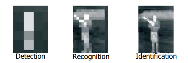
The normal limit for the target distance of an IR camera is the size in pixels that the object will appear in the image and the number of pixels that are required to identify or extract the required information about the target. For example, as shown in the image, do you want to Detect, Recognize, or Identify the person in the image? The number of pixels you place on an item allows you to make the determination. For temperature measurement, an object should appear as at least a 5 × 5-pixel object in the image. 10 × 10 will yield even better results.
Q: Can I create 3D orthomosaics with my thermal data sets?
A: FLIR does not currently offer tools for thermal orthomosaics. For mapping operations, there are third party thermal orthomosaic services experience in processing images from thermal cameras. Currently, the ability to retain pixel-level radiometric temperature data is lost in the process of creating the ortho.
Q: What software is best for my thermal data set or operation?
A: Different cameras offer different file types and characteristics. Also, different applications have different requirements. Higher-resolution (320 × 256 or greater) thermal cameras can achieve a better level of detail by saving images in the -R.JPEG format and processing them with the free FLIR Tools application. This combination allows radiometric parameters to be adjusted post-flight and provides a simple framework for generating reports. CSV files of pixel values can also be created for additional processing. FLIR Thermal Studio offers batch processing for jobs that require a large number of files.
Q: What gimbal should I use for my Duo Pro R?
A: FLIR does not have specific recommendations for gimbals. Third-party gimbal suppliers (such as Gremsy) will have compatibility information for their products.
Q: How do I get video downlink from my camera?
A: For real-time video downlink, FLIR UAS cameras provide either NTSC/PAL composite or HDMI video. Check the camera datasheets to see which video output formats are compatible with third-party downlink systems.
Q: What is radiometry, and do I need it?
A: Radiometry is the measurement of the amount of radiation coming from a target, usually in terms of the target temperature. This feature is not always required for a given application. Radiometry is available only on premium thermal cameras. Thermal images often provide information that is easily interpreted by a user. For example, when one solar panel appears noticeable cooler than its neighbors or has a more uneven temperature than its neighbors, it is not necessary to know the magnitude of the difference in degrees— that solar panel should be checked. Similarly, when one vehicle shows warm brakes and a warm engine while others don’t, it is clear which vehicle was driven last without knowing the actual temperatures. When a suspicious person is seen hiding in vegetation, it is not necessary to know the person’s body temperature. Very many thermal imaging applications can be performed in this way without absolute temperature measurement. In some cases, a repeatable absolute measurement needs to be made. For example, when checking a transformer on a power pole, there may be no nearby transformers for comparison. For applications like this, a radiometric camera would be used, and the estimated surface temperature would be compared to established limits.
Q: Which color palette is best for my mission?
A: Many laboratory and military users of thermal cameras use the White Hot or Black Hot palette. Exaggerated color palettes can be used to highlight changes in temperatures that may otherwise be difficult to see, but they bring out additional noise and may mask key information. Color palettes should be chosen to show pertinent details of an image without distraction. If the FLIR R.JPEG radiometric image file format is used, the color palette can be changed after a flight using the free FLIR Tools application or FLIR Thermal Studio Pro.
Q: When should I use isotherms?
A: The isotherm feature highlights a range of temperatures with a color change. This can make it easy to find objects of a known temperature against a background of a different temperature or to highlight areas of a field that have exceeded a certain temperature. Isotherm is offered only on radiometric cameras. The accuracy of the isotherm feature is the same as the temperature measurement accuracy.
Q: How accurate is my temperature reading?
A: There are two items to consider regarding temperature: thermal sensitivity and measurement accuracy. Thermal sensitivity is the ability of the camera to detect differences in temperature. Most uncooled IR sensors in UAS operations have a thermal sensitivity of <50 mK.
Temperature measurement accuracy varies based on the range selected. For example:
- +/- 5°C or 5% of readings in the -25°C to +135°C range
- +/- 20°C or 20% of readings in the -40°C to +550°C range
The radiometric parameters are environmental details that affect the amount of thermal radiation emitted by an object or that affect the amount of radiation that reaches the camera. For example, for a given surface temperature, an object with an emissivity of 48% will emit half the thermal radiation that an object with an emissivity of 96% emits. Objects with lower emissivity will also reflect more thermal radiation from their surroundings. For this reason, the emissivity and background temperature must be known and considered for an accurate estimation of an object’s temperature. Long distances or atmospheric obscurants will affect the amount of thermal radiation that the camera will receive from an object. These parameters can be set in the camera for real-time display. If the FLIR R.JPEG radiometric image file format is used, these parameters can be adjusted later using the free FLIR Tools application or FLIR Thermal Studio Pro.
Q: Do I need special training to operate a thermal camera?
A: For many uses of thermal cameras, the information presented is so intuitive that little or no training is required to get results. There are free videos on FLIR Delta and other FLIR web pages that can be used to get started. Operators with more experience will get even more from the thermal images. Some applications require formal training and certification for fast, consistent collection and interpretation of thermal data. Comprehensive training and certification services are available from the FLIR ITC infrared training center.
Q: What is the minimum and maximum temperature range of the camera?
A: Camera specifications are listed on each product datasheet. The Duo Pro R can reliably measure temperatures from -25°C to 135°C, but it can also detect targets from -40°C to 550°C with reduced accuracy and reduced sensitivity. Objects outside these ranges will appear as solid light or dark regions with no surface detail.
Q: Are my thermal images automatically geotagged?
A: If GPS data is available to the camera, images stored in the FLIR radiometric R.JPEG format will be geotagged. Thermal images in TIFF format will also be geotagged, but since there is no official geotag format in TIFF 6.0 format, the tags used may not be readable by all programs. Geotag information for video files is stored in an SRT file with the time of day. Many video display programs can view SRT file data as subtitles.
Some FLIR UAS cameras have a built-in GPS receiver. If that receiver has GPS lock, the location data will be stored. If there is no GPS receiver in the camera, files may still be geotagged if the location data is sent by the vehicle to the camera via MAVlink.
Q: Does my sUAS camera come with a calibration certificate?
A: Each camera is shipped with a Certificate of Conformity as part of the shipping paperwork. This certificate will list the cameras that it covers. Periodic calibration is currently not offered for FLIR UAS cameras.
Q: What causes the halo or vignetting in my images?
A: Thermal cameras work best when all the camera components are at the same temperature. In a drone camera, this is almost never the case. Heat from electronics and gimbal motors inside the housing reaches one end of the camera while the lens is cooled by the propeller slipstream. This usually results in the outside edge and corners of the image appearing cooler than the center. This “image non-uniformity” is often described as vignetting, halo, or if one of the more extreme color palettes is applied, a “purple ring.” The camera compensates for this to some extent but the dynamic nature of the issue makes completely preventing the effect difficult.
Q: How can I reduce halo effects or vignetting in my images?
A: All thermal cameras have some image non-uniformity. This often takes the form of cooler edges and corners, which causes a halo effect. The more extreme color palettes available on your camera are created to exaggerate any details in the image. A low-contrast scene has fewer details, so the colors will be applied to noise or other artifacts. In most cases, it is easier to interpret thermal images with the White Hot or Black Hot palette, as these show more consistent contrast. Also, scenes with people or other warm objects will “stretch” the colors, making the halo less noticeable.
Q: How do I convert pixel data to temperature?
A: Only pixel values from radiometric thermal cameras like the FLIR Vue Pro R or the Duo Pro R can be converted to temperature values. For these cameras, the tiff file pixel values have already been converted to a temperature based on the target emissivity, background temperature, and other radiometric parameters present in the camera at the time the image was taken. These values are stored with a scale factor. In order to be converted to degrees Kelvin, they need to be multiplied by 0.04 (if the camera was in high gain mode) or 0.4 (if the camera was in low gain mode). High gain is the default mode and low gain is only entered when temperatures exceed 135° C. To convert from Kelvin to degrees Centigrade, subtract 273.15 from the value in Kelvin. For example, a tiff file pixel value of 7500 (decimal) 7500*0.04 – 273.15 is approximately 27°C.
The FLIR radiometric R.JPEG files are more flexible than tiff files. R.JPEG files can be opened using FLIR Tools and the radiometric parameters can be adjusted to different values to make corrections after flight. This allows estimating temperature values for different targets with different emissivity values, or to add values not known at the time of flight. Various spot meters and areas available from FLIR Tools can be used interactively to analyze the image. To create a CSV file of all the pixel temperature values from an R.JPEG file, open the file in FLIR Tools, make any required radiometric parameter adjustments, and then right-click anywhere in the image. A menu will come up with an option to create a CSV file. From this selection, you can choose to create a CSV file for the entire image or of any measurement points or boxes that you’ve created in the image.
Q: My phone does not connect to the camera. What can I do?
A: The FLIR UAS app requires access to the Bluetooth transceiver of the camera. It is possible for various security or battery saving add-ons and protocols to interfere with this. Application settings should be checked to make sure that the app has the required access. The Bluetooth setting should be checked to confirm that the transceiver in the phone is turned on. Uninstalling and re-installing the app may re-establish the correct permissions. Turning the phone all the way off and back on again is another thing that can help in some cases.
Strong transmitters, such as video downlinks, telemetry, or remote controllers may affect the phone’s transceiver, even if they don’t operate in the same band. Trying different locations for the phone may help. If performed safely, turning off unneeded transmitters may help resolve issues.
Lastly, FLIR UAS cameras turn their Bluetooth transceivers off if there is no Bluetooth activity for several minutes. The Bluetooth LED will light blue when enabled. To reactivate, press the Bluetooth button on the camera until the LED turns blue again.
Q: Can I change the lens on my thermal camera?
A: This is not recommended and will void the camera warranty. Removing the lens on a thermal camera exposes the detector window to dust and other contaminants from the air and to debris from the lens threads. Any dust particle on this window will create an image artifact. The window coatings are too delicate to be cleaned.
Q: Why does the image appear to “Freeze” sometimes before returning to normal operation?
A: IR cameras perform a NUC (Non-Uniform Correction) prior to adjusting level and span. This automatically corrects the minor detector drift that occurs as the scene and environment changes. The camera will also perform this operation on its own from time to time. Think of this as setting all the pixels back to a base reference point.